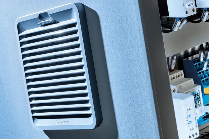
7F Series – Full Range

Thermal Regulation – Filter Fans
Controlling temperature in enclosures is important. Electrical and electronic components used within have an ambient temperature range for optimum performance. If this ambient temperature exceeds the maximum specification levels, performance can be degraded and components damaged leading to repair and downtime. Often all that is required is to circulate air; introducing cool air from the outside using Filter Fans.

Air Movement - what is the best way to move or cycle airflow in an enclosure?
Moving the air within the enclosure is equally important as is the size and CFM of the fan selected. If ambient temperature and cooling needs are minimal, all that may be required is a Filter Guard allowing heat dissipation naturally. More often additional intervention is necessary. Using a combination of Filter Fans and Filter Guards will increase input of outside cool air and exhaust of ambient heat created. Finder has both – ‘draw-in’ and ‘reverse-flow’ fan options to aid in designing the most optimum solution.

A common approach is to have the Filter Fan placement towards the bottom of the enclosure drawing in cooler air, and the Filter Guard at the top where the heat collects. This setup would require a 7F.20 Series ‘draw-in’ Filter Fan and a 7F.02 Series Filter Guard shown in the example to the left.
A variation to the above example may see utilizing a 7F.21 ‘reverse flow’ Filter Fan at the top and the 7F.02 Filter Guard at the bottom. Using the fan to move the hot air directly from the top of the enclosure. Depending on airflow requirements one could consider a reverse flow as well as a draw-in fan to increase airflow or increasing the number of overall units installed in the enclosure if larger fan sizes are not practical.
How do we choose the size of fan? How many fans or CFM are required? In the past, this next step included math and perhaps graphs or charts, but now …
… enter the FINDER THERMO-CONFIGURATOR …

Finder developed a web based Thermo-Configurator to make these calculations easy and efficient. From selecting metric or US data, temperature, panel type and power, it is a guided step by step process to reach the final results.

Finder added extra features in the configurator tool:
Beyond thermoregulation, add lighting to your project with our custom designed 7L panel lights. Print or share the final results among colleagues or end customers. The summary not only provides part numbers, but also links to the datasheets – no searching around the web site.
Calculations done easy by Finder!!

Mounting
Ease and flexibility of mounting is important. Unlike axial or ‘muffin’ fans with a separate metal or plastic guard, the Filter Fan is an all in one component. With each fan Finder ships a template for cut out information and 4 screws. For most panels (sidewalls 1.2 – 2.4 mm in thickness) simply mount the fan into the cutout until the built-in installation clips snap in place.

The installation clips are optimized for 1.5 mm thick material. If the enclosure is constructed of heavier gauge material, or there is added concern of vibration, the included screws cover material thickness from 1 mm thru 2.5 mm.
Care must also be considered for the reverse flow 7F.21 high speed size 4 and both size 5 fans. Here the CFM is high enough that screws are recommended for installation.

Maintenance

Another consideration for airflow is maintenance. In each Filter Fan and Filter Guard there is a filter media or ‘mat’ to filter out the dust and particles prior to them getting into the enclosure. This media does require periodic maintenance to insure proper airflow. Cleaning or replacement of the media is easy with the construction of Finder’s 7F Filter Fans. The 7F design includes a hinged cover for quick and easy inspection or replacement of the filter media. Depressing the tab at the top allows the cover to swing downwards exposing the media. After maintenance or replacement simply move the grill closed until the tab snaps back in latching the cover in place.

7F - The Range …
- Operating voltage: 24 V DC, 120 or 230 V AC (50/60 Hz)
- Air volume (17…412)CFM (free flow)
- Air volume (10…277)CFM (with Exhaust Filter installed in cabinet)
- Push-in connections
- Available reverse air-flow (code 7F.21)
- Protection category: IP54 / UL Type 12
- Size 1 up to Size 5
- Housing and cover gray (RAL 7035) or black (RAL 9004)

Exhaust Filter
- Quick replaceable filter
- Protection category: IP54 / UL Type 12
- Size 1 up to Size 5
The size of the Exhaust Filter should match the size of the Filter Fan to achieve the best ventilation within the cabinet.


Book a Finder-15 Video Sales Call to discuss your configuration and thermoregulation products in detail.


